Tuesday, November 10, 2009

Phase transformations and phase diagrams

In contrast to pure metals, which solidify at a constant temperature - freezing point, alloys solidify over a range of temperature, depending on the alloy components and their concentrations.

In course of solidification and subsequent cooling of solid alloy processes of phase transformations take place. The phases compositions and their quantities change with the temperature.

Phase diagrams are used for quantitative description of the phase transformation and changes.

Phase diagram of an alloy system is a graphical presentation of the relationships between the phases compositions and their relative amounts at any given temperature and under equilibrium conditions.

Despite the fact, that in real metallurgical processes, especially in the processes, occurring in solid state, the equilibrium conditions are not reached, phase diagram is a very useful instrument of analysis and quantitative evaluations of the alloy behavior.

Phase diagram of an alloy system consisting of two components is called binary phase diagram.

There are three main types of binary phase diagrams :

These three diagrams and combinations of them describe behavior of most of binary alloys.

Complete solid and liquid solution diagram

The typical diagram of this type is illustrated by the figure below.

The diagram has two curves – liquidus (equilibrium conditions of liquid phase with first solid crystals – primary crystals) and solidus (equilibrium conditions of last liquid with nearly complete solid).

complete solubility.png

Consider solidification of an alloy with concentration C. When the alloy temperature is higher than TL , single liquid phase exists (point M on the diagram).

When the temperature reaches the value TL (point M1 on the liquidus curve) solidification starts. According to solidus curve (point N1 )the first solid crystals have different composition – C1.

Further cooling of the alloy causes changing of the liquid phase composition according to the liquidus curve and when the alloy temperature reaches a certain intermediate value T (position MT ), liquid phase of composition Cy and solid phase of composition Cx are in equilibrium.

Relative amounts of the two phases are determined by their compositions and may be calculated by the “lever rule” :

WS / WL = MTY / MTX

or

WS / WL = (CY-C) / (C-CX)

Where:

WS – weight of the solid phase;

WL – weight of the liquid phase;

MTY and MTX – length of the corresponding lines in the diagram.

Solidification ends at the temperature TS and the last remainders of liquid phase have the composition C2 (according to the point F2 on the liquidus curve).

to top

Eutectic diagram

Eutectic phase diagram describes behavior of the alloys, two components of which are completely soluble in liquid state and entirely insoluble in solid state.

This diagram has two liquidus curves, starting from the freezing points of the two metals and intersecting in a minimum point – eutectic point.

eutectic.png

Consider solidification of an alloy with concentration C. When the alloy temperature is higher than TL , single liquid phase exists (point M on the diagram).

When the temperature reaches the value TL (point M1 on the liquidus curve) solidification starts. The primary crystals, forming in this case are the crystals of the metal “A”.

Further cooling of the alloy causes enrichment of the liquid phase with the metal “B” according to the liquidus curve and when the alloy temperature reaches a certain intermediate value T (position MT ), liquid phase of composition Cy and solid phase, consisting of “A” crystals, are in equilibrium.

At the temperature equal to TE (eutectic temperature) formation of the primary crystals stops and the remainding liquid phase , having composition CE (eutectic composition), transforms to an intimate mixture of small “A” and “B” solid crystals. This is the eutectic phase transformation.

Relative amounts of the primary crystals and the eutectic mixture may be calculated by the “lever rule” :

WP / WE = (CE-C) / C

Where:

WP – weight of the primary crystals;

WE – weight of the eutectic mixture.

to top

Eutectic diagram with partial solubility of the components in solid state

This kind of phase diagram is a “hybrid” ofthe diagram with complete solid and liquid solution and the eutectic diagram (the metals are completely soluble in liquid state and entirely insoluble in solid state).

eutectic with solid solution.png

Consider solidification of an alloy with concentration C. When the alloy temperature is higher than TL, single liquid phase exists (point M on the diagram).

When the temperature reaches the value TL (point M1 on the liquidus curve) solidification starts. According to solidus curve the first solid crystals (primary crystals) of the α-phase have composition C1.

Further cooling of the alloy causes changing of the liquid phase composition according to the liquidus curve and when the alloy temperature reaches a certain intermediate value T (position MT ), liquid phase of composition Cy and solid α-phase of composition Cx are in equilibrium.

At the temperature equal to TE (eutectic temperature) formation of the primary crystals stops and the remainding liquid phase , having composition CE (eutectic composition), transforms to a finely devided mixture of small solid crystals of α-phase and β-phase (eutectic phase transformation).

At this temperature all α-phase crystals have composition Cα and all crystals of β-phase have composition Cβ.

Relative amounts of the α-phase primary crystals and the eutectic mixture may be calculated by the “lever rule” :

WP / WE = M2E / M2N

or

WP / WE = (CE-C) / (C- Cα)

Where:

WP – weight of the α-phase primary crystals;

WE – weight of the eutectic mixture;

Just below the eutectic temperature TE the alloy consists of two solid phase: α-phase and β-phase, relative amounts of whichis determined by the “lever rule” :

Wα / Wβ = M2F / M2N

or

Wα / Wβ = (Cβ-C) / (C- Cα)

Where:

Wα – weight of the α-phase;

Wβ – weight of theβ-phase;

During further cooling solid solution phases (α-phase and β-phase) change their compositions according to the solvus curves NN3 and FF3 .

Solvus curve determins formation of solid solution phase from another solid solution phase – similar to liquidus curve.

At the temperature T3 α-phase crystals have composition Cα and all crystals of β-phase have composition Cβ.

Hypo-eutectic alloys

If an alloy composition C is lower, than eutectic composition CE , solidification of the alloy starts from formation of the primary crystals of α-phase according to the left branch of the liquidus curve. These alloys are called hypo-eutectic.

Hyper-eutectic alloys

If an alloy composition C is higher, than eutectic composition CE , solidification of the alloy starts from formation of the primary crystals of β-phase according to the right branch of the liquidus curve. These alloys are called hyper-eutectic.

Eutectoid phase transformation is analogous to the eutectic transformation, however it occurs with a solid solution phase, breaking up into a mixture of two finely divided phases of different compositions.

to top

Eutectic diagram with intermetallic compound

Intermetallic compound (valence compound) is a phase, having chemical composition equal to a fixed simple ratio, like CuZn,Cu3Sn, Mg2Pb, etc.

Sometimes intermetallic compounds exist over a range of composition, differing from the valence law. Intermetallic compounds of this sort are called electron compounds or intermediate solutions.

An example of a phase diagram with intermetallic compound AB2 is shown in the figure below.

diagram with compound.png

This diagram may be considered as a combination two different diagrams: A- AB2 and AB2-B.

to top

Peritectic diagram

Sometimes a solid solution phase, which has already been formed, andthe residual liquid phase react and form another solid solution phase or intermetallic compound, having a composition between the compositions of the liquid and the first solid. This is peritectic transformation (peritectic reaction).

An example of a phase diagram with peritectic transformation is shown in the figure:

peritectic.png

Consider solidification of an alloy with concentration C. When the alloy temperature is higher than TL , single liquid phase exists (point M on the diagram).

When the temperature reaches the value TL (point M1 on the liquidus curve) solidification starts. According to solidus curve (point N1 )the first solid crystals (primary crystals) of the α-phase have composition C1.

Further cooling of the alloy causes changing of the liquid phase composition according to the liquidus curve and when the alloy temperature reaches a certain intermediate value T (position MT ), liquid phase of composition Cy and solid α-phase of composition Cx are in equilibrium.

At the temperature equal to TP (peritectic temperature) formation of the α-phase crystals stops and the remainding liquid phase , having composition CL reacts with α-phase crystals , forming β-phase of composition CP (peritectic phase transformation).

At this temperature remaining α-phase crystals have composition Cα and all crystals of β-phase have composition CP (peritectic composition).

Relative amounts of the α-phase crystals and the liquid phase just above the peritectic transformation may be calculated by the “lever rule” :

Wα / WL = (CL-C) / (C- Cα)

Where:

Wα – weight of the α-phase crystals;

WL – weight of the liquid phase;

Just below the peritectic temperature TP the alloy consists of two solid phase: α-phase and β-phase, relative amounts of whichis determined by the “lever rule” :

Wα / Wβ = (CP-C) / (C- Cα)

Where:

Wα – weight of the α-phase;

Wβ – weight of theβ-phase;

During further cooling solid solution phases (α-phase andβ-phase) change their compositions according to the corresponding solvus curves.

At the temperature T3 α-phase crystals have composition Cα and all crystals of β-phase have composition Cβ.

If the alloy composition is exactly equal to peritectic composition CP , α-phase and liquid phase are consumed comletely in the peritectic reaction.

Alloys with composition C lower than CP , some quantity of α-phase remains after the peritectic reaction (it may be calculated by the “lever rule”).

If the alloy composition C is higher than CP , some liquid phase remains after the peritectic reaction. This remaining liquid transforms to β-phase during the further cooling.

Electrode potentials (corrosion)

Dr. Dmitri Kopeliovich


Electrode potential is a fundamental conception of electrochemistry and corrosion theory. It helps to predict the direction and intensity of an electrochemical process (eg. corrosion) and allows to control it.

Oxidation and reduction

There are two meanings of the term oxidation.

The common (narrow) meaning of oxidation - chemical reaction (combining) between Oxygen and any other element resulting in formation of oxide.

For example calcium and oxygen combine forming calcium oxide:

Ca + 1/2O2 = CaO

In chemistry the term oxidation has a wider meaning:

Oxidation - is a chemical process, in which an element loses one or more of its electrons giving it/them up to another element.

The element receiving the electrons is not necessarily oxygen.
For example the reaction between calcium and chlorine is considered oxidation:

Ca + Cl2 = CaCl2

In this reaction an atom of calcium oxidizes when it gives up two its electrons to two atoms of chlorine.

Both reactions may be presented in ionic form as follows:

Ca = Ca2+ + 2e-

Reduction is a chemical process opposite to oxidation, in which an element gains one or more electrons given by another element.

For example reduction of copper from copper oxide:

CuO + H2 = Cu + H2O

In this reaction positive ion of copper receives two electrons from two atoms of Hydrogen.
Reduction of copper in ionic form may be presented as follows:

Cu2+ + 2e- = Cu

Hydrogen losing its electron oxidizes in this reaction.

Oxidation of an element is always accompanied by reduction of another element therefore the reaction is often called oxidation-reduction or redox.

to top

Galvanic cell

Single electrode cell.png If a piece of a metal M is dipped into a solution capable to dissolve it the metal begins to oxidize giving the electrons e- to the metal specimen and forming positive ions M+ transferring to the electrolyte solution.

As a result a potential difference Δφ between the metal piece and electrolyte forms.

The absolute value of the potential difference can not be measured since the measurement would mean inserting another electrode into the electrolyte and formation another potential difference between them.

For relative measurements of potentials of various metals in various solutions galvanic cell is used.
Typical galvanic cell consists of two metallic electrodes (eg. Zn and Cu) immersed into different solutions (ZnSO4 and CuSO4). The solutions are electrically connected by a salt bridge (a piece of filter paper soaked in a salt solution).
The metallic electrodes are connected to a high resistance voltmeter.
The galvanic cell is schematically described by the cell notation:

Zn(s)|ZnSO4(aq,m1)||Cu(s)| CuSO4(aq,m2)

(s) indicates solid;
(aq, m1), (aq, m2) indicate aqueous solution of concentration m1 and m2
A single vertical line | indicates a boundary between e metallic electrode and the electrolyte;
The double vertical line || indicates the salt bridge between the two electrolytes.

It is accepted that the negative electrode is written in the left and the positive electrode - in right part of the diagram.

Galvanic cell.png

In this galvanic cell the zinc electrode is anode. It oxidizes and gives up the electrons of the atoms dissolving in the electrolyte in form of positive ions:

Zn = Zn2+ + 2e-

The copper electrode is cathode. The dissolved copper ions gain electrons from the metallic electrode and converts to solid metal depositing on the cathode surface:

Cu2+ + 2e- = Cu

If the value of the electric current is negligible (high resistance voltmeter is used) the measured potential difference between the electrodes is equal to the electomotive force (EMF) of the galvanic cell.

The measurement of electromotive force are usually made under standard conditions:

  • Temperature: 77ºF (25ºC, 298K);
  • Pressure of gases: 1 atm;
  • Electrolyte solution activity (concentration): 1 M (1 mol/dm3).

Electromotive force measured under standard conditions has a notation E0.
EMF of a galvanic cell is a resulting sum of potential differences of the anode and cathode:

E0 = Ecathode - Eanode

to top

Standard electrode potential

Standard electrode potential is the electromotive force measured in the Galvanic cell consisting of the half-cell with the electrode under standard conditions and the half-cell with the standard hydrogen electrode.

Standard electrode potential.png

Standard hydrogen electrode (SHE) consists of a platinum foil coated by platinum black (platinum powder), which is dipped into an acidic solution with concentration of hydrogen ions (H+) 1M and which is in contact with gaseous hydrogen bubbling around the electrode.
Platinum does not take part in the reaction but it serves as a catalyst for oxidation-reduction reaction of hydrogen.
Standard electrode potentials are measured relatively to the standard hydrogen electrode, potential of which is defined as 0 volt:

E0 = E0R - E0(H/H2) = E0R

When a standard electrode potential is measured the electrode is connected to the positive terminal of the voltmeter and the standard hydrogen electrode is connected to the negative terminal of the voltmeter.

to top

Electrochemical series

Standard electrode potentials of metals are arranged in electrochemical (galvanic) series.

The greater the negativeness of a standard electrode potential the greater the tendency of the element to oxidize (dissolve).
Noble (non-reactive) metals having positive value of the standard electrode potential are located in the bottom part of the table.

Electrode E0
Li+/Li -3.045
Rb+/Rb -2.925
K+/K -2.925
Cs+/Cs -2.923
Ba2+/Ba -2.905
Ca2+/Ca -2.866
Na+/Na -2.714
Mg+/Mg -2.37
Al3+/Al -1.66
Ti2+/Ti -1.630
Zr4+/Zr -1.539
Mn2+/Mn -1.179
V2+/V -1.175
Cr2+/Cr -0.913
Zn2+/Zn -0.763
Cr3+/Cr -0.744
Fe2+/Fe -0.44
Cd2+/Cd -0.403
Co2+/Co -0.277
Ni2+/Ni -0.250
Sn2+/Sn -0.136
Pb2+/Pb -0.126
Fe3+/Fe -0.037
H+/H2 0.000
Cu2+/Cu +0.337
Cu+/Cu +0.521
Ag+/Ag +0.799
Hg2+/Hg +0.851
Pd2+/Pd +0.987
Pt2+/Pt +1.188
Au3+/Au +1.50
Au+/Au +1.692


to top

Nernst equation

If an electrode is not under standard conditions the electrode potential may be calculated according to the Nernst equation:

E = E0 - (RT/nF)*lnCion

Where:
E0 - Standard electrode potential, V;
R - gas constant R=8.3143 J/(mol*K);
T - temperature, K;
n - number of electrons transferred;
F - Faraday constant F=96500 C/mol (C-coulombs);
Cion - molar activity (concentration) of ions.

At the temperature 298K the Nernst equation may be presented as follows:

E = E0 - (0.059/n)*lnCion

Nernst equation is used for constructing Pourbaix diagrams (E / PH diagrams), which help to determine the direction of electrochemical processes with metals in water solutions.

Welding precipitation hardening stainless steels

Welding austenitic stainless steels

Austenitic stainless steels include series 200 and 300 (examples: 201, 202, 216, 302 ,304, 310, 316, 321 ,347).

Due to their austenitic structure the steels have low thermal conductivity (half of that of ferritic steels) and therefore lower heat input is required for welding.
coefficient of thermal expansion of austenitic stainless steels is relatively high resulting in larger thermal distortions and internal stresses of the welded parts, which increase suceptibility of the weld to hot cracks. The presence of small amount of ferrite (about 5%) decreases the risk of hot cracks due to the ability of ferrite to dissolve low melting impurities.
Austenitic stainless steels are also characterized by lower wettability and higher viscosity of the liquid metal in weld pool, which may cause welding defects.
Commonly the compositions of filler materials for welding austenitic stainless steels match the steels compositions. The un-stabilized steels 201, 202,301, 302, 304, 305 are welded by the filler material of type 308 (21%Cr, 10%Ni).
308 alloy contains more chromium and nickel than 304, which results in:

  • suppression of martensite formation ;
  • controllable amount of ferrite limiting suceptibility of the weld to hot cracks.

SENSITIZATION
One of the possible welding defects of austenitic stainless steels is sensitization.
At the temperatures 900-1400ºF (482-760ºC) chromium carbides form along the austenite grains. This causes depletion of chromium from the grains resulting in decreasing the corrosion protective passive film.
This effect is called sensitization.
Sensitization is depressed in low carbon steels (0.03%) designated with suffix L (304L, 316L).
Formation of chromium carbides is also avoided in stabilized austenitic stainless steels (321, 347) containing carbide forming elements like titanium, niobium, tantalum, zirconium. Stabilization heat treatment of such steels results in preferred formation of carbides of the stabilizing elements instead of chromium carbides.

Welding ferritic stainless steels

Ferritic stainless steels include part of the steels from the series 400 (examples: 405, 409, 430, 442, 446).

The main welding problem of ferritic stainless steel is growth of ferrite grains caused by heating. Coarse grain structure results in low toughness of the weld material.
In order to prevent the grain coarsening the preheat is limited to 150-450ºF (65-230ºC). Low carbon ferritic steels (405, 409) are welded without preheating. Heat input should also be limited particularly when thick parts are welded (thicker, than 0.25”/6mm). Weld toughness may be improved if an Austenitic stainless steels filler material is used.

Commonly filler materials containing equal or excessive amount of chromium are used for welding ferritic stainless steels.
Some parts may be welded without filler material.

Welding martensitic stainless steels

Ferritic stainless steels include series 500 and part of the steels from the series 400 (examples: 403,410, 414, 416, 420, 422, 431, 440, 501, 502, 503, 504).

Weldability of martensitic stainless steels is low because of their sensitivity to cold cracks formation:

  • Martensitic structure of the steels is determined by high carbon content, which reduces the steel ductility and therfore increase the sucsceptibility to cracks.
  • Martensitic transformation causes changes of grains volume due to to the changes of the crystall lattice. These changes produce internall stresses, which increase the risk of cracks.
  • Martensitic stailess steels easily pick-up and dissolve Hydrogen from the atmosphere and other sources, which may cause hydrogen embrittlement.


In order to prevent cracks formation the welded parts should be preheated to 400-570ºF (204-300ºC). Measures should be taken in order to diminish hydrogen pick-up during the welding process (dry flux, shielding gas). Post-weld heat treatment at 1000-1200ºF (540-650ºC) of high carbon (> 0.2%) martensitic steels is required for improvement of the steel toughness.

Commonly filler materials, in which contents of chromium and carbon match the composition of the welded parts, are used for welding martensitic stainless steels.
Weld toughness may be improved if an Austenitic stainless steels filler material (308, 309) is used.

Welding austenitic-ferritic (Duplex) stainless steels

austenitic-ferritic (Duplex) stainless steels (examples: 2205) have a mixed austenitic-ferritic structure and commonly contain 0.1-0.3% of Nitrogen.

Weldability of Duplex stainless steels is good.
In order to prevent nitrogen loss during welding shielding gas containing nitrogen is used.
Proper filler materials and controlled heat input help to obtain the required balance between the austenitic and ferritic phases.

Precipitation hardening stainless steels are categorized into three groups: martensitic (17-4PH, 15-5PH), semiaustenitic (17-7PH, PH 15-7Mo) and austenitic (17-10P, A286).

Commonly filler materials, composition of which close to the composition of the welded parts, are used for welding precipitation hardening stainless steels .

Weldability of austenitic precipitation hardening stainless steels is poor because of their susceptibility to hot cracks. Limited heat input and welding of parts in solution treated condition are required for diminishing risk of cracks. Nickel alloys (nickel-chromium-iron) are used as filler materials for welding austenitic precipitation hardening stainless steels.

Tungsten Inert Gas Arc Welding (TIG, GTAW)

Dr. Dmitri Kopeliovich


Tungsten Inert Gas Arc Welding (Gas Tungsten Arc Welding) is a welding process, in which heat is generated by an electric arc struck between a tungsten non-consumable electrode and the work piece.

The weld pool is shielded by an inert gas (Argon, helium, Nitrogen) protecting the molten metal from atmospheric contamination.

The heat produced by the arc melts the work pieces edges and joins them. Filler rod may be used, if required.

Tungsten Inert Gas Arc Welding produces a high quality weld of most of metals. Flux is not used in the process.

Tungsten Inert Gas Arc Welding.png
Advantages of Tungsten Inert Gas Arc Welding (TIG, GTAW):

  • Weld composition is close to that of the parent metal;
  • High quality weld structure
  • Slag removal is not required (no slag);
  • Thermal distortions of work pieces are minimal due to concentration of heat in small zone.


Disadvantages of Tungsten Inert Gas Arc Welding (TIG, GTAW):

  • Low welding rate;
  • Relatively expensive;
  • Requres high level of operators skill.

Shielded Metal Arc Welding (SMAW)

Dr. Dmitri Kopeliovich


Shielded metal arc welding (Stick welding, Manual metal arc welding) uses a metallic consumable electrode of a proper composition for generating arc between itself and the parent work piece. The molten electrode metal fills the weld gap and joins the work pieces.

This is the most popular welding process capable to produce a great variety of welds.

The electrodes are coated with a shielding flux of a suitable composition. The flux melts together with the electrode metallic core, forming a gas and a slag, shielding the arc and the weld pool. The flux cleans the metal surface, supplies some alloying elements to the weld, protects the molten metal from oxidation and stabilizes the arc.
The slag is removed after Solidification.

Shielded metal arc welding.png
Advantages of Shielded Metal Arc Welding (SMAW):

  • Simple, portable and inexpensive equipment;
  • Wide variety of metals, welding positions and electrodes are applicable;
  • Suitable for outdoor applications.


Disadvantages of Shielded Metal Arc Welding (SMAW):

  • The process is discontinuous due to limited length of the electrodes;
  • Weld may contain slag inclusions;
  • Fumes make difficult the process control.

Principles of arc welding

Dr. Dmitri Kopeliovich


Arc welding is a welding process, in which heat is generated by an electric arc struck between an electrode and the work piece.

Electric arc is luminous electrical discharge between two electrodes through ionized gas.

Any arc welding method is based on an electric circuit consisting of the following parts:

  • Power supply (AC or DC);
  • Welding electrode;
  • Work piece;
  • Welding leads (electric cables) connecting the electrode and work piece to the power supply.


arc welding.png

Electric arc between the electrode and work piece closes the electric circuit. The arc temperature may reach 10000°F (5500°C), which is sufficient for fusion the work piece edges and joining them.

When a long join is required the arc is moved along the joint line. The front edge of the weld pool melts the welded surfaces when the rear edge of the weld pool solidifies forming the joint.

Types of weld joints are shown in the figure:

Weld joints.png

When a filler metal is required for better bonding, filling rod (wire) is used either as outside material fed to the arc region or as consumable welding electrode, which melts and fills the weld pool. Chemical compositions of filler metal is similar to that of work piece.

Molten metal in the weld pool is chemically active and it reacts with the surrounding atmosphere. As a result weld may be contaminated by oxide and nitride inclusions deteriorating its mechanical properties. Neutral shielding gases (argon, helium) and/or shielding fluxes are used for protection of the weld pool from atmospheric contamination. Shields are supplied to the weld zone in form of a flux coating of the electrode or in other forms.

Metal Inert Gas Welding (MIG, GMAW)

Dr. Dmitri Kopeliovich

Metal Inert Gas Welding (Gas Metal Arc Welding) is a arc welding process, in which the weld is shielded by an external gas (Argon, helium, CO2, argon + Oxygen or other gas mixtures).

Consumable electrode wire, having chemical composition similar to that of the parent material, is continuously fed from a spool to the arc zone. The arc heats and melts both the work pieces edges and the electrode wire. The fused electrode material is supplied to the surfaces of the work pieces, fills the weld pool and forms joint.

Due to automatic feeding of the filling wire (electrode) the process is referred to as a semi-automatic. The operator controls only the torch positioning and speed.

Metal Inert Gas Welding (MIG, GMAW).png
Advantages of Metal Inert Gas Welding (MIG, GMAW):

  • Continuous weld may be produced (no interruptions);
  • High level of operators skill is not required;
  • Slag removal is not required (no slag);


Disadvantages of Metal Inert Gas Welding (MIG, GMAW):

  • Expensive and non-portable equipment is required;
  • Outdoor application are limited because of effect of wind, dispersing the shielding gas

TIP TIG Welding Pictures


TIP TIG pipe welding TIP TIG Welding Inconel TIP TIG Welding Inconel two TIP TIG, Faster Wire Feeds TIP TIG Welding 3x Faster Superior TIP TIG Torch control
TIG TIG Welding vs Traditional TIG TIP TIG Stainless Steel Welding Manual TIP TIG Weld Quality
TIP TIG Automated Welds
TIP TIG Torch. OverHead
TIP TIG Torch. Semi Automated
TIP TIG Welding Stainless, Picture TIP TIG Welding Picture, Stainless Vessel TIP TIG Manual Welding Pictures
TIP TIG Pictures, Vertical
TIP TIG Welding Stainless Tubes
TIP TIG  Manual Welds

Traditional TIG Welding Information


Tungsten Inert Gas Welding - Tig Welders


For the world's most effectice
TIG weld Process, Click on TIP TIG.


Question
. Ed please provide some guidelines and general data for establishing automated TIG welding parameters

Answer. When automated TIG welding, an important first requirement is determine the approximate weld current required for the specific welds. Once the approximate weld current range is determined, then select the correct tungsten electrode size. The following enables the correct size tungsten electrode.


TIG Welding Parameters:

TUNGSTEN SIZE AND APPROX.
WELD CURREN
T RANGE FOR DCEN.


Tungsten
Ceriated
Lanthanaum

0.020
(0.5mm)

0.040
(1.0mm)
Tungsten
DCEN Amp
Range

5 - 20A

15 - 70A
BEST EQUIPMENT FOR ALUMINUM WELDS IS A POWER SOURCE WITH AN

EN-EP BALANCE CONTROL. WITH THIS EQUIPMENT THERE IS NO NEED FOR AC CURRENT / TUNGSTEN CONCERNS. WITH ALUMINUM SIMPLY USE A LANTHANUM OR CERIATED TUNGSTEN AND USE THE SIMILAR CURRENT AS USED WITH DCEN,


0.062
(1.6mm)

70-140A

3/32
(2.4mm)

130- 210A

1/8
(3.2mm)

200- 310A

5/32
(4mm)

250 - 500A

Try and ensure with
the TIG tungsten selected that the weld current

frequently used is not > 80% of the recommended weld amp range.


Anyone who has worked with TIG Welders and automated and orbital TIG systems, knows the TIG weld quality is highly dependent on retaining the shape and quality of the tungsten tip. Weld start data is critical with automated TIG welding applications. Tungsten life is improved with a start ramp up from a low current start point then ramp to the operating current.

The Cobra TIG 150A power source is shown below. This is one of the best, economical, small pulsed TIG power sources designed for "orbital tube welds" that I ever had the pleasure working with. No bell and whistles, just logical, practical process control features. The equipment delivers consistent, controlled weld results and the company that provides the equipment provides excellent equipment product support. The Cobra TIG power source is available from MK products California.


TIG TUNGSTEN PROFILES:


For automated TIG welds with AVC controls or good tungsten to work height control, with the use of correct tungsten size and weld parameters, both a tungsten point and a tungsten with a small flat spot with a 20 to 30 degree angle should be able to get the tungsten through at least a high duty 6 to 8 hours of arc on time without tungsten regrind or change,


PULSED TIG WELDING DATA:


Use pulsed as a solution to a problem that occurs with a consistent TIG arc. However remember with most pulsed carbon steel or stainless steel TIG welding applications pulsed TIG the most consistent arc, is an arc without a pulse


PEAK TO BACK GROUND THIN PARTS: If using pulsed, set the weld current for the "average pulsed current" For example welding a part 0.040 thick requires approx. 40 amps. To attain 40 amps start out with a peak current to back ground ratio of 3 to 1. Back Ground - 20 amps. Peak current - 60 amps, this provides an average weld current of 40 amps.

PULSED WIDTH OR TIME. The time at which the peak current is maintained. The more sensitive the part to weld heat the smaller the width or the less percentage of time. Start in the range of 30 to 50 %.

PULSED FREQUENCY. Examine the pulsed overlap weld pattern 60 to 80 percent overlap is good. For thin metals <0.030>


Pulsed TIG is not required with the
superior TIP TIG process


GENERAL TIG DATA:


Tungstens.
Avoid radioactive concerns from thoriated electrodes, use Lanthium or Ceriated Tungstens. Information below.

[] With those low current TIG applications under 20 amps, grind the tip of the tungsten to 20 degrees to a point.

[] With steel applications that require > 20 amps, to avoid the tip melting and becoming a tungsten inclusion in the weld, grind the tip to an included angle of 20 - 30 degrees and add a small flat spot approx. 0.005 to 0.010 on the tip.


TIG TUNGSTEN TYPES:


For steel and alloy steel applications, avoid radiation concerns with thoriated tungsten and use 1.5% Lanthium or Ceriated Tungstens.


FOR CONSISTENT ARC STARTS AND CONSISTENT WELD QUALITY TIG "ARC LENGTH" IS CRITICAL:

APPROX. ARC LENGTH. Gap between tungsten and weld surface,

Arc length (AL) with applications that weld at 15 to 30 amps = 0.025 - 033
Arc length (AL) with applications that weld at 30 to 50 amps = 0.030 - 038
Arc length (AL) with applications that weld at 50 to 70 amps = 0.040
Arc length (AL) with applications that weld at 70 to 150 amps = 0.070 - 0.080
Arc length (AL) with applications that weld > 150 amps = 0.125 - 0.165


TIG WELDING SPEEDS - TIG WELD, TECHNIQUES

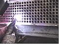
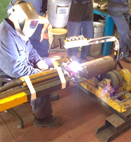
If you don't know the traditional TIG weld speed, start at 4 - 5 ipm, (with TIP TIG start at 12 - 15 ipm) then change the speed to suit the desired weld size and penetration requirements. Use a fore hand position with the tungsten to help break up the oxides in front of the welds.


RAMP DOWN CURRENT FOR WELD CRATER REDUCTION
AND TUNGSTEN PROTECTION.


For TIG crater fill, ramp down and back stepping is common. About 3 to 4 mm from end of weld, ramp down from the weld current to 1-5 amps for 1 to 2 seconds...


ORBITAL TIG WELDING AND REQUIRED WELD SCHEDULES.

Orbital TIG welds typically require a minimum of 4 weld parameter schedules to compensate for the increased weld heat that occurs as the TIG weld travels 360 degrees around the tube. For example a weld schedule may drop the weld current by 10 - 20% between each of the 4 schedules as the weld heat builds up during the TIG torch rotation. 
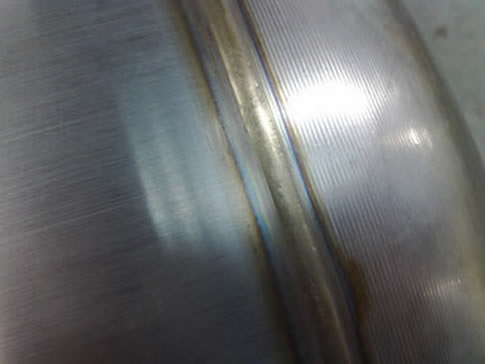
Note, the smaller and thinner the tube welds, the faster the weld heat builds up.

Orbital Tube Typical Weld Procedure.
Provide ramp up weld start 20 amps leading into weld schedule 1. Schedule 1 travels from 12 to 3 o'clock with 60 amps. For the schedule 2. the torch travels 3 to 6 o'clock at 55 amps. For weld schedule 3. The TIG torch travels between 6 to 9 o'clock at 50 amps. For the final weld schedule 4. The torch travels between 9 to 12 o'clock at 48 amps. Then apply the crater fill and finish data that could ramp the current down as low as 1 amp.


For great orbital tube or pipe auto TIG equipment check out MK and AMI, California. For manual, conventional TIG applications and comparing Miller, ESAB and Lincoln TIG power sources, my choice is typically Miller followed by ESAB. FRONIUS also has some interesting products.

Question: Ed. We are TIG welding Aluminum. When we use the AC we can set the AC balance control towards electrode positive or negative and yes are welders all use different setting, each swearing that their balance setting is the best. Any logic we should apply as to the optimum setting. Thanks for your web site. Kyle

Answer. With AC welding we get both EP and EN. With EP, the majority of the electrons will flow to the tungsten tip while the larger positive gas molecules hit the alum surface breaking up the alum oxide skin. Unfortunately EP sends to many electron to the tungsten tip and the heat build will melt the tip end. To avoid the tip damage, with all TIG welds we use EN (electrode negative)in which the electrons are driven away from the tungsten to the work. With AC alum welds and a balance control, it's beneficial to use an arc with a little amount of EP added, so set that start balance control at 80% EN and 20% EP. Check the weld cleaning etch if its too wide decrease EP, not enough increase EP. For a tighter narrower TIG plasma increase EN, for the opposite decrease EN.


T
IG WELD GASES: Argon is the most economical gas and when provided in liquid form eliminates concern for gas contamination which is common in high pressure cylinders that have not been purged before use or when the cylinders have been previously used for MIG gas mixes that contain reactive gases (O2 or CO2). For most common welds, Use a flow rate of 10 to 20 cuft/hr, start out at 15 cuft/hr. For high speed or deeper TIG penetration welds, flow rates will typically be increased between 20 and 50 cuft/hr.


When requiring higher energy welds, before considering costly argon - helium or argon - hydrogen gas mixes, for any TIG application start out on a piece of scrap with straight argon (99.995% pure) and ensure the weld current required is compatible with the tungsten size utilized. It's a fundamental fact, that for all weld applications and all alloys that will require less than 200 amps, that straight argon is the logical choice. Its also a fact that if you need high energy TIG weld you should be using TIP TIG which rarely requires helium or hydrogen gases.

I believe all TIG applications benefit from the use a gas lens. The use of gas lens also allows for greater tungsten extension which is beneficial on joints with tight restriction.


WELD SPEEDS AND AUTOMATED TIG APPLICATIONS: If you using high current and are utilizing the largest possible tungsten, to further increase weld speeds (automated applications only) with steel applications, try a 60 - 70% helium / 40- 30% argon mix. With austentitic and some nickel welds, the addition of hydrogen in the range of 5 - 30% may provide faster and cleaner welds. With most austenitic 300 series applications, nitrogen may be used for the back up gas. Remember that when TIG welding, with approx. 90% of TIG applications, you will get ther job done with straight argon.

Note: Ed developed three of the most common MIG gas mixes used in North America, visit the MIG gas section if you want to get the saesmanship out og gas selection.

Consider argon with 5 - 30% hydrogen if you want more weld wetting or faster faster weld speeds. Remember an increase in weld speed may have little value if the weld cycle time is measured in seconds. The hydrogen addition to argon can increase arc stability on specific, very thin low amp applications <10>


Note: TIP TIG enables the fastest possible TIG weld speeds and typically requires only argon:


PRE FLOW - POST FLOW. Starting the arc and finishing the arc without sufficient pre - post gas flow will cause instant damage to the tungsten. Using a controlled pre- and post flow is critical if you wish to retain the integrity of the tungsten / weld and minimize tungsten inclusions in your weld. Examine the contact tip at the arc start for the first inch of weld if the tip end gray or black your pre - flow gas is inadequate. Then examine the tip at the weld completion and look for the same contamination to tell you if the post flow time is effective. For TIG welds in which many welds are required it may pay to keep the shielding gas flowing continuously.
FLOW RATES: As mentioned , use a flow rate of 10 to 20 cuft/hr and start out at 15 cuft/hr. Gas flow can be increased as weld sizes get bigger. With some automated applications, increasing gas flow can also enable a slight increase in the weld fusion and weld speed

OZONE FORMATION: Ozone forms in both MIG and TIG arcs. The greater the weld current density and the greater the reflective weld surface, the greater the ozone content. For more info, visit MIG weld gases at this site.


TIG Weld Safety & Thoriated Tungsten Concerns:


Thorium is a radio active alloy used in the manufacture of tungsten arc welding electrodes to assist in arc starting. Although companies involved in welding have been using thoriated electrodes for many years, the industry is becoming more mindful of their potential health hazards and the micro amounts of radiation levels found in the grinding dust and environment where TIG welders work.

The following are notes, warnings, and recommendations form various organizations on the use of thoriated tungsten welding electrodes


American Welding Society: "Thorium is radioactive and may present hazardous by external and internal exposure. Alternatives tungsten types are available If welding is to be performed in confined spaces for prolonged periods of time or if electrode grinding dust might be ingested, special precautions relative to ventilation and dust disposal should be considered. The user should consult appropriate safety personnel."
Tungsten. Standard Manufacturer's Warning: "Thorium dioxide is a naturally occurring radioactive element. It is an alpha emitter and, as such, its primary hazard lie in inhalation of dust/fumes." "Thorium dioxide has been identified as a carcinogen by the NTP and IARC." (These quotes are from Osram Sylvania MSDS sheets).


The Welding Institute: Thorium is a radioactive element. The HSWE has recommended to factory inspectors that , where thoriated tungsten electrodes are not necessary, users should be encouraged to look for alternatives.Cancer Assessment: Thorium dioxide has been identified as a carcinogen by the National Toxicology Program and International Agency for Research on Cancer.


TIG TUNGSTEN SAFETY QUESTION. We use Thoriated TIG electrodes in our factory. We have been told by a sales rep that these electrodes are are associated with health hazards. Can we consider switching to Ceriated or Lanthanated TIG electrodes? What type of tungsten should you replace the thoriated with when using AC and DC TIG welding?


Answer: For welding steels consider a tungsten with 2 percent cerium or a tungsten with 1 to 2 percent of lanthanum. Ceriated and lanthanated tungsten electrodes are equal to other electrodes in terms of their weld properties and are superior in some areas.

In contrast to "pure tungsten" the advantages of a ceriated or lanthanated electrode are:
[] Outstanding in the low current range.
[] Excellent ignition and re-ignition performance.
[] More durable a longer service life.
[] Excellent weld current carrying capacity.
[] Maintains a point instead of tendency to balling.


Remember regular TIG is obsolete.
Welcome to TIP TIG:


Aluminum TIG welds have special considerations,


Welding Aluminum with pure tungsten and AC current. The AC current will result in a ball at the tungsten tip, The rounded tip results from the high arc energy generated from the EP portion of the AC arc. With an alloyed rare earth tungsten when welding aluminum with AC the tungsten can be pointed with a flat added at the tip, this can provide welding benefits

As mentioned pure tungsten balls up, producing a wider, less intense plasma arc cone that can result in arc wandering. A rare earth tungsten used in combination with square wave technology that enables a greater ratio of EN rather than EP maintains a point and lets you use smaller tungsten. This type of tungsten provides a more focused arc so you can more precisely control heat input and weld bead profile. For a pointed electrode, use a truncated (flat) poi
nt as an overheated tip point can melt or fall into the weld.


What benefits are attained from using TIG inverter (balance control power sources) with the rare earth tungstens?

Through the benefits of balance AC control, some power sources allow up to 90 percent EN in the AC cycle with variable output frequency (20 to 250 Hz) you can dramatically reduce the heat at the tungsten tip and direct the majority of electrons to the work piece. This provides;

* Narrower heat affected zones
* Improved control over weld depth-to-width ratios.
* Initiate the weld puddles much faster.
* Faster weld travel speeds.
* Reduction in porosity.
* Less tungsten and gas consumption.
* Eliminate arc wandering.
Aluminum TIG Welding

Question
: Ed We are trying to AC - TIG weld a plug in an Alum 60 series tube. The tube rotates. The tube is only 12 mm OD, and to add to the problems it's only 0.050 thick. The plug is the same alloy, however it's solid, 1/8 thick 3/8 in length and fits in the end of the tube. The pulsed weld is made between the plug surface and tube end. We have extensive GTAW issues in controlling the weld fluidity in this single pass weld and frequently melt through the thin tubes.

TIG Welding Answer.
This is a difficult, automated TIG application. The following adds to your weld issues.


[a] The tube is thin aluminum, rapid heat build up..
[b] The tube is small diameter, rapid heat buildup.
[c] The plug thickness is different to the tube creating different weld heat requirements.
[d] The plug length is short creating rapid heat build up in contrast to the tube which is a good heat conductor.
[c] AC with pure tungsten is used. The weld arc width and length may change with variations in the tungsten length and shape.

SOMETIMES WHEN THE PROBLEM IS GENERATED BY WELD HEAT, THE TIG WELD SOLUTION IS MORE WELD PASSES.

The answer to this difficult weld issue may lie in the opposite of what you would expect. Instead of a high current single pass (single tube rotation) weld try two or possibly three smaller weld passes.

[1] First start out with a low weld current TIG pass. This weld pass will preheat the tube and plug and reduce the alum oxides.

[2] For the second pass, slightly ramp up the weld current, just enough to let the tube and plug alum melt and form a weld.

[3] For the third pass if necessary, use one more tube rotation. Use a lower current then the weld pass, this pass is to blend the weld.

[4] Ensure you use at least a 3 - 5 second current tail out with the finish weld current less than 5 amps.

[5] The best weld equipment for this application is to use a balance wave and set the EN between 80-90%.


~~~~~~~~~ AC GTAW Arc Rectification~~~~~~~~


For those of you that use AC current on your TIG aluminum applications and you may wonder about that occasional plasma arc instability that may occur in the TIG arc. The following is a brief description of AC arc rectification.

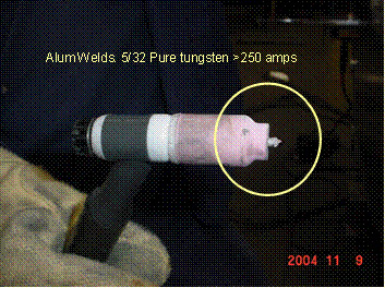
During the AC cycle, the tungsten is both positive and negative and the electrons flow in two directions 120 times per-second from the tungsten to work and from the work to the tungsten. First the tungsten in the negative mode is a superior conductor than the metals being welding. When the AC cycle is in its negative mode the electrons will flow from tungsten to work. During the negative mode we have more stable electron flow than when the electron flow in the positive cycle in which the electrons flow from negative alum metal surface to the positive tungsten tip.

Another reason for AC rectification is the condition of the aluminum weld surface. For example when welding multipass TIG welds one weld pass will remove the alum metal surface oxide, the next pass made on top of the weld may present a cleaner weld surface, (a weld surface that presents less surface oxides). When the alum m
etal surface has less impurities (less oxides) the HF used to reignite the AC arc may have a difficult time as oxides add to arc stability, (that's one of the benefits of oxygen or CO2 in a MIG gas to weld steel).

Remember it's the argon gas molecules and tungsten positive cycle that provides the arc cleaning action. The positive cycle is when the electrons flow from the work (breaking up the minuscule aluminum surface oxides) to the tungsten, this provides the arc cleaning action. Once the alum oxides have decreased from the weld surface its harder for the HF to reignite the arc so we see arc stability issues also affected by the condition of the alum weld surface.
Today we use square wave weld equipment to minimize the effects of AC rectification however the arc rectification will still occur, it's just less noticeable.


03/2009 Regular TIG is obsolete.
Welcome to TIP TIG: